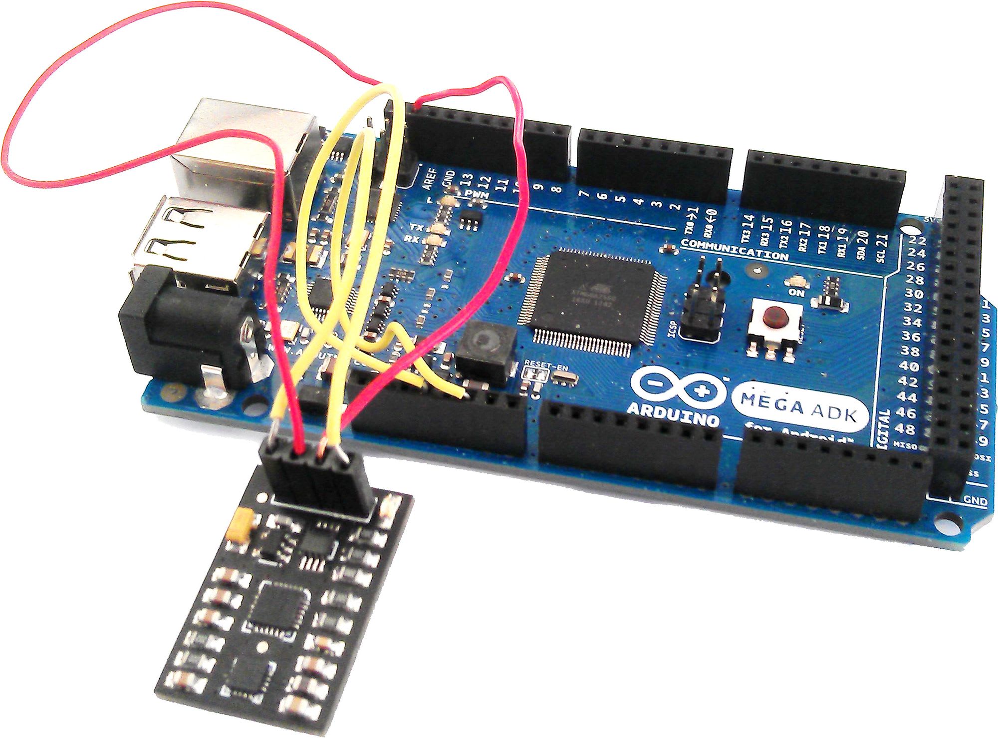
Arduino 2560 ADK with a 9DOF sensor board (MPU 6050)
In order to monitor the movement of my robot I looked for an IMU sensor board. At the end I bought a 9 DOF transducer offered by Flydurino.net. It is similar to the “original” Flydurino board (Freeimu 0.4.3) but does not provide an altimeter. Its interfaces are limited too and do not cover an interrupt channel or a SPI interface. But it is much cheaper 🙂
Jeff Rowberg wrote a powerful library to address I2C devices that integrates the MPU 6050 already. But I missed an example code that shows how to use all sensors (especially the HMC5883l) on this board in a common application. It is connected to via sub I2C on the IMU. For this purpose I extended the code proposed by @muzhig on i2cdevlib. Additional useful information can be found on Arduino MPU 6050.
Comments, improvements or hints are welcome!
// ---------------------------------------------------------------------------
// Receive all measurements from an 9 DOF sensor board.
//
// Sebastian Zug
// Otto-von-Guericke University, Magdeburg, Germany
// 09/2013
// ---------------------------------------------------------------------------
//
// Structure:
//
//                                           Sub I2C
//                                        ______^ ______
//                                       |              |
// ----------
//  Arduino  |               ----------------          -------------
//  2560     |- 3.3 V ------ | MPU 6050     |          |  HMC5883  |
//           |- GND ---------| Acceleration,|---SDA ---|  Compass  |
//           |- SDA ---------| Gyro, Temp   |---SCL ---|           |
//           |- SCL ---------|              |          |           |
//           |               ----------------          -------------
//-----------
//                       |___________________ _______________________|
//                                           V
//                                   Integrated IMU sensor
//
// Pull-up resistors are integrated in the sensor board.
//
// IMPORTANT: When I connect the sensor board to a 5V power supply, it was
//            not possible to realize a I2C connection in this case. I made
//            some experiments with additional pull-upps on the I2C but
//            without any results.
//
// ---------------------------------------------------------------------------
//
// It exists a very good library for I2C communication based on Arduino "Wire"
// provided by Jeff Rowberg. It integrates specific controllers as MPU 6050
// and HMC 5883. Take a view on https://github.com/jrowberg/i2cdevlib
//
// The example was implement with i2cdevlib Version and extends the existing
// MPU_6050_raw // example. It uses the code proposed by @muzhig on i2cdevlib
// https://github.com/jrowberg/i2cdevlib/issues/18
// ---------------------------------------------------------------------------

#include "Wire.h"
#include "I2Cdev.h"
#include "MPU6050.h"
#include "HMC5883L.h"

// The default I2C address is defined
// MPU 6050 - 0x68 - MPU6050_DEFAULT_ADDRESS
// HMC5883L - 0x1E - HMC5883L_DEFAULT_ADDRESS
MPU6050 mpu6050;
HMC5883L hmc5883l;

int16_t ax, ay, az;
int16_t gx, gy, gz;
int16_t mx, my, mz;
double temp;

#define LED_PIN 13
bool blinkState = false;

// this method is just used to collect different setSlave operations
void setSlaveControl(uint8_t slaveID){
    mpu6050.setSlaveEnabled(slaveID, true);
    mpu6050.setSlaveWordByteSwap(slaveID, false);
    mpu6050.setSlaveWriteMode(slaveID, false);
    mpu6050.setSlaveWordGroupOffset(slaveID, false);
    mpu6050.setSlaveDataLength(slaveID, 2);
}

void setup() {
    // join I2C bus (I2Cdev library doesn't do this automatically)
    Wire.begin();
    // initialize serial communication
    Serial.begin(9600);

    Serial.println("Initializing I2C devices...");

    mpu6050.initialize();
    if (mpu6050.testConnection()){
      Serial.println("MPU6050 connection successful");
    }
    else {
      Serial.println("MPU6050 connection failed");
    }

    // configuration of the compass module
    // activate the I2C bypass to directly access the Sub I2C
    mpu6050.setI2CMasterModeEnabled(0);
    mpu6050.setI2CBypassEnabled(1);

    if (hmc5883l.testConnection()) {
        Serial.println("HMC5883l connection successful");
        hmc5883l.initialize();

        // unfourtunally
        // hmc5883l.setMode(HMC5883L_MODE_CONTINUOUS);
        // does not work correctly. I used the following command to
        // "manually" switch on continouse measurements
        I2Cdev::writeByte(HMC5883L_DEFAULT_ADDRESS,
                          HMC5883L_RA_MODE,
                          HMC5883L_MODE_CONTINUOUS);

        // the HMC5883l is configured now, we switch back to the MPU 6050
        mpu6050.setI2CBypassEnabled(0);

        // X axis word
        mpu6050.setSlaveAddress(0, HMC5883L_DEFAULT_ADDRESS | 0x80);
        mpu6050.setSlaveRegister(0, HMC5883L_RA_DATAX_H);
        setSlaveControl(0);

        // Y axis word
        mpu6050.setSlaveAddress(1, HMC5883L_DEFAULT_ADDRESS | 0x80);
        mpu6050.setSlaveRegister(1, HMC5883L_RA_DATAY_H);
        setSlaveControl(1);

        // Z axis word
        mpu6050.setSlaveAddress(2, HMC5883L_DEFAULT_ADDRESS | 0x80);
        mpu6050.setSlaveRegister(2, HMC5883L_RA_DATAZ_H);
        setSlaveControl(2);

        mpu6050.setI2CMasterModeEnabled(1);
    } else {
        Serial.println("HMC5883l connection failed");
    }

    // activate temperature MPU 6050 sensor
    mpu6050.setTempSensorEnabled(true);

    // configure Arduino LED for
    pinMode(LED_PIN, OUTPUT);
}

void loop() {

    // read raw heading measurements from device
    mx=mpu6050.getExternalSensorWord(0);
    my=mpu6050.getExternalSensorWord(2);
    mz=mpu6050.getExternalSensorWord(4);

   // To calculate heading in degrees. 0 degree indicates North
    float heading = atan2(my, mx);
    if(heading < 0)
      heading += 2 * M_PI;

   // read raw accel/gyro measurements from device
   mpu6050.getMotion6(&ax, &ay, &az, &gx, &gy, &gz);

   // see MPU 6050 datasheet page 31 of 47
   temp=((double) mpu6050.getTemperature()) /340.0 + 36.53;

   Serial.print(ax); Serial.print("\t");
   Serial.print(ay); Serial.print("\t");
   Serial.print(az); Serial.print("|\t");
   Serial.print(gx); Serial.print("\t");
   Serial.print(gy); Serial.print("\t");
   Serial.print(gz); Serial.print("|\t");
   Serial.print(heading * 180/M_PI); Serial.print("|\t");
   Serial.println(temp,3);

    // blink LED to indicate activity
    blinkState = !blinkState;
    digitalWrite(LED_PIN, blinkState);
}